Circuit schematics are the bridge between conceptual electrical design and physical realization of a printed circuit board assembly, or pcba.
44+ Electrical Schematic Symbols Receptacle Gif. When drawing electrical and telecom plan, you need to display electrical circuit, schematics, electrical wiring, digital circuits and house electrical plans, etc. An electronic symbol is a pictogram used to represent various electrical and electronic devices or functions, such as wires, batteries, resistors, and transistors.
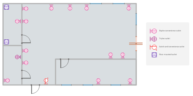
How To use House Electrical Plan Software | Electrical ... from conceptdraw.com
This physics video tutorial explains how to read a schematic diagram by knowing what each electric symbol represent in a typical electrical circuit. There are many electronic symbols in electronic circuits that are used to represent or identify a basic electronic or electrical device. For some electronic circuits this symbol is used for the 0v (zero volts) of the power supply, but for mains electricity and some radio circuits it really means the earth.
Then we'll talk about how those symbols are connected on schematics to create a model of a circuit.
Electrical circuit schematic symbols are graphical sign, that is used to design electronic, electrical circuit schematic diagram. Circuit schematics are the bridge between conceptual electrical design and physical realization of a printed circuit board assembly, or pcba. Here are charts to help you to identify symbols on electrical schematics. Electrical symbols, electrical schematic symbols.