Hydraulic symbols provide a clear representation of the function of each hydraulic component.
11+ Hydraulic Schematic Symbols Reservoir Pictures. Hydraulic symbols explained, understand how to read hydraulic diagram symbols. Hydraulic and pneumatic picture symbols for fluid power schematics, define their function in engineering use this page as a reference to find common schematic symbols used in fluid power schematics, hydraulic schematics, pneumatic schematics.
Mariners Repository: Hydraulics Part 1 - Direction Control ... from 4.bp.blogspot.com
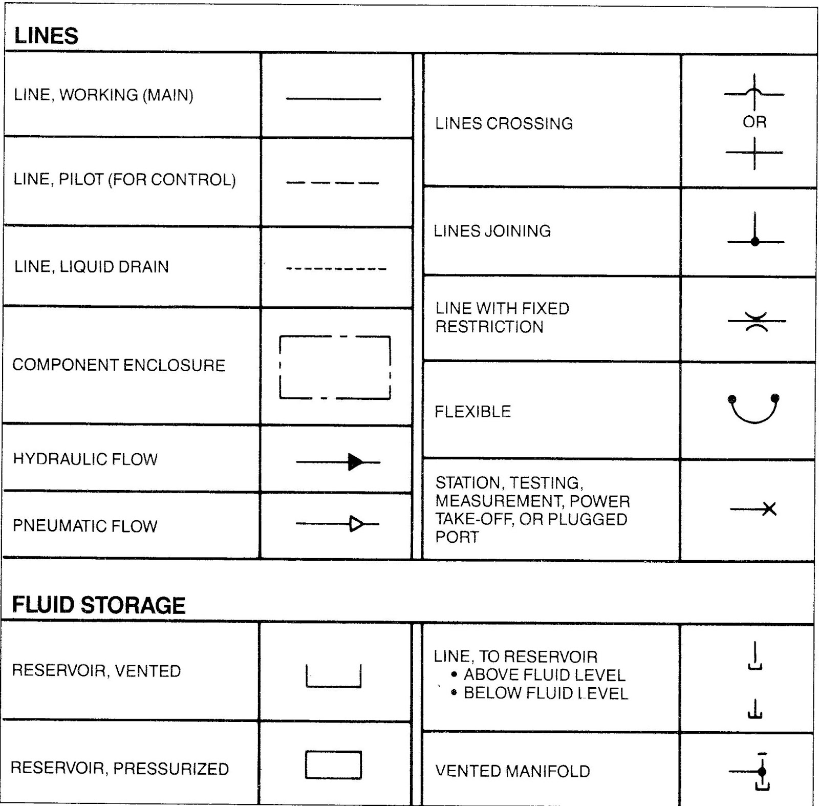
The above level return line terminates at or slightly below the upright legs of the. Different symbology is used when dealing with systems that operate with fluid power. Pressurized reservoirs are shown as capsules.
Hydraulic symbols explained, understand how to read hydraulic diagram symbols.
The following are to links of iso hraulic schematic symbols and other useful data. No grinding or welding operations should once the correct pressures have been established, note them on the hydraulic schematic for future. Hydraulic symbols provide a clear representation of the function of each hydraulic component. Laying each symbol out on the page in the same sequence the components are used in the circuit allows people.