40+ 4 Relay Module Schematic Background. 10 a @ 24 vdc. Each relay has a normally open (no) and a normally closed (nc) the following schematic shows how to connect the module to an arduino, i have only shown one device (lightbulb) connected to one relay.
Each relay has a normally open (no) and a normally closed (nc) the following schematic shows how to connect the module to an arduino, i have only shown one device (lightbulb) connected to one relay.
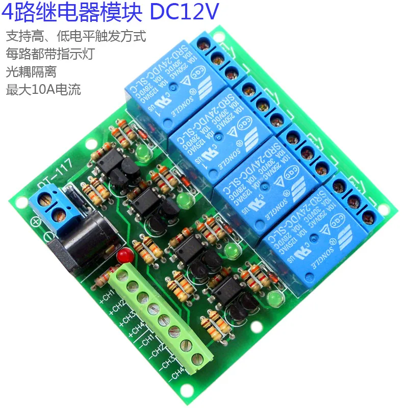
Full technical support for electronics, robotics equipments. 4 relays are included in this module, with nc ports means normally connected to com and no ports means normally open to com. How to use relay to control high power load? Below is the arduino code which we have used to demonstrate this relay module: