This relay module must be wired as outsider cites;
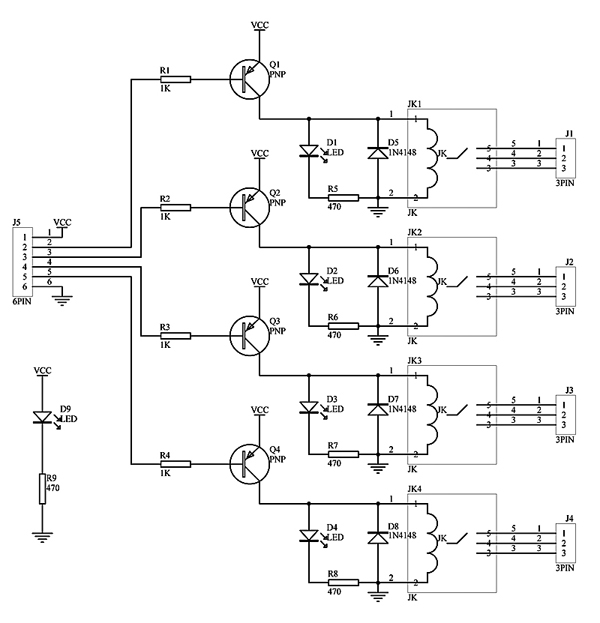
12+ 2 Channel Relay Module Schematic Images. Four mounting holes of 3.2 mm each. The four channel relay module and the two channel relay module work the same way.
esp8266 - Can I use a 3.3v GPIO to control an opto ... from arduino-direct.com
As parts availability was primary concern so whole schematic is designed around very basic components , the system is built around only one microcontroller pic16f877a which is quite. The driver schematic everyone is discussing cannot be correct. There are other models with one, four and eight channels.
Op amplifier temperature switch fan control schematic circuit diagram.
Do not touch any wires that are connected to mains voltage. The driver schematic everyone is discussing cannot be correct. To send a command to the. As parts availability was primary concern so whole schematic is designed around very basic components , the system is built around only one microcontroller pic16f877a which is quite.