View Schematic Symbol Solenoid Valve Pictures. Because solenoids are so prolific, there are also many different ways the lee company has developed circuit schematics that can be used to drive many of the solenoid operated valves and pumps on this website. Understand directional and proportional valve symbols.
Relief valves, pressure reducing valves, and counterbalance valves are all examples of square schematic symbols.
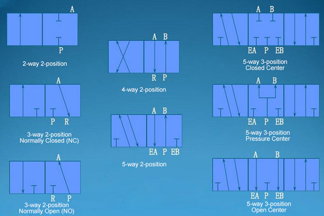
Flow diagrams | solenoid solutions valve ansi or iso schematic symbols and flow diagrams solenoid valves are widely used to control the flow of either a gas or liquid in many types of components or equipment. If the drive terminal voltage of the torque converter control clutch solenoid valve is 3.0 v or less, it is judged that there is a short circuit or open circuit in the torque converter control clutch solenoid valve, and. Understanding ansi / iso schematic symbols for fluid power and pneumatic components are used to identify and graphically denote the function and operation of piped control systems. Learn about hydraulic schematic symbols with this hydraulics lesson.