View Schematic Symbol Gate Images. Schematic symbols are used to represent different electronic components and devices in circuit it does not take too long to learn what the different circuit symbols mean. Symbol and special character codes frequently used in autocad almost equal to, angle, boundary line, centerline, delta, electrical phase, flow line, identity, initial length, monument line, not equal.
They would both have the same value in you assign whatever you wish, u1 might be suitable, to the schematic symbol's reference property.
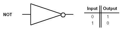
Basic tutorial on creating a cmos xor gate schematic symbol and layout using cadence virtuoso.simulation not included as viewers are encouraged to implement. A logic gate is an idealized model of computation or physical electronic device implementing a boolean function, a logical operation performed on one or more binary inputs that produces a single binary output. Electrical symbols and electronic circuit symbols are used for drawing schematic diagram. Some of the schematic symbols in these libraries have changed!