Are you ready for a barrage of circuit components?
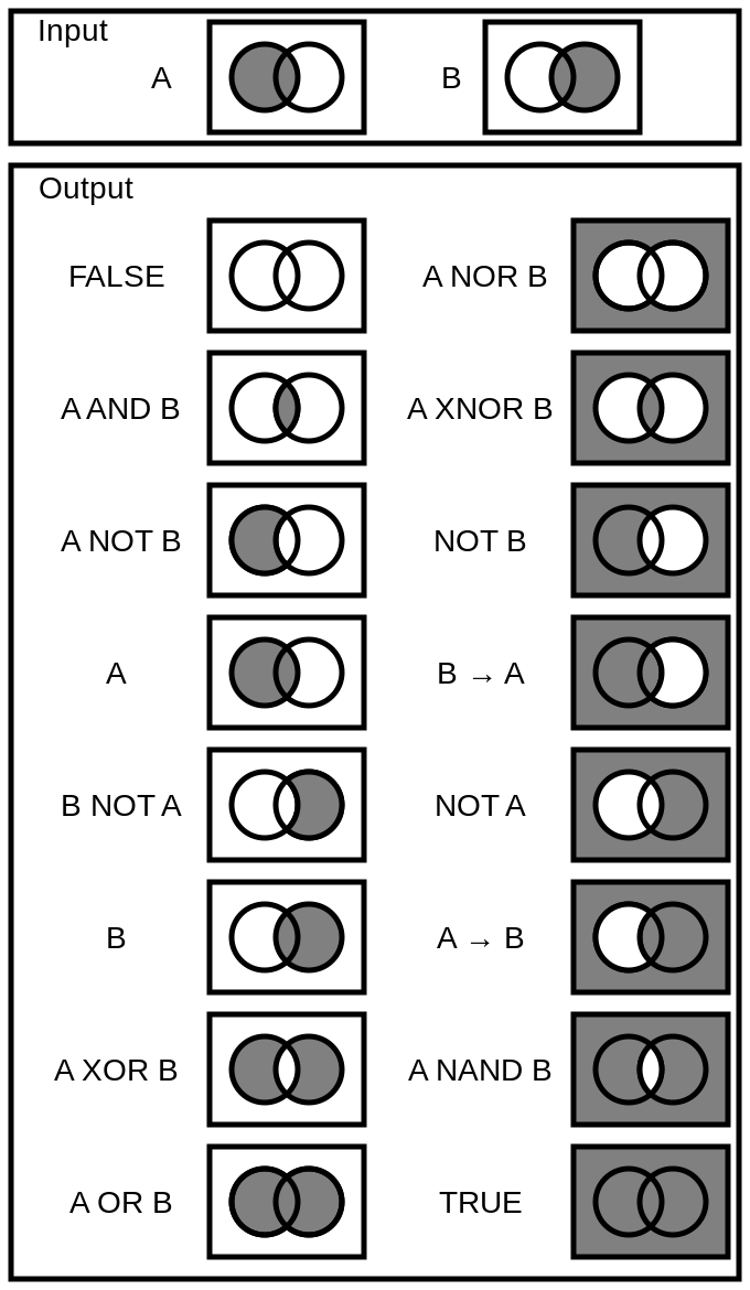
View Schematic Logic Symbol Background. Logic gate with two or more inputs that outputs a logic 0 (low) when all of its inputs are high at logic 1 (equivalent to not + and). Schematic diagrams with graphical symbols are used to show the electrical connections and functions of a specific circuit.
File:LogicGates.svg - Wikipedia from upload.wikimedia.org
But you don't need to memorize them all. Some of the schematic symbols in these libraries have changed! An overview of the most used schematic symbols in electronic circuits.
To be able to read schematics you must know the schematic symbols.
The ic is not relevant to the schematic, where it's about the circuit's if your schematic symbol would represent the package you would have to draw all connections for. Learn about hydraulic schematic symbols with this hydraulics lesson. In logic, a set of symbols is commonly used to express logical representation. The basic logic gates are used to perform fundamental logical functions.