This is the circuit diagram of zener diode tester which tests zener diodes with breakdown voltages extending up to 120 volts.
View Schematic Diagram Of Zener Diode Images. As we have gone through the first part of the article we know what is zener diode and what is the basic principle of operation. Although zener diodes provide a quick and easy way zener diodes can be also applied as effective ripple voltage filters, just as it's used the figure below demonstrates the basic circuit diagram.
34 Zener Diode Circuit Diagram - Wiring Diagram Database from i.ytimg.com
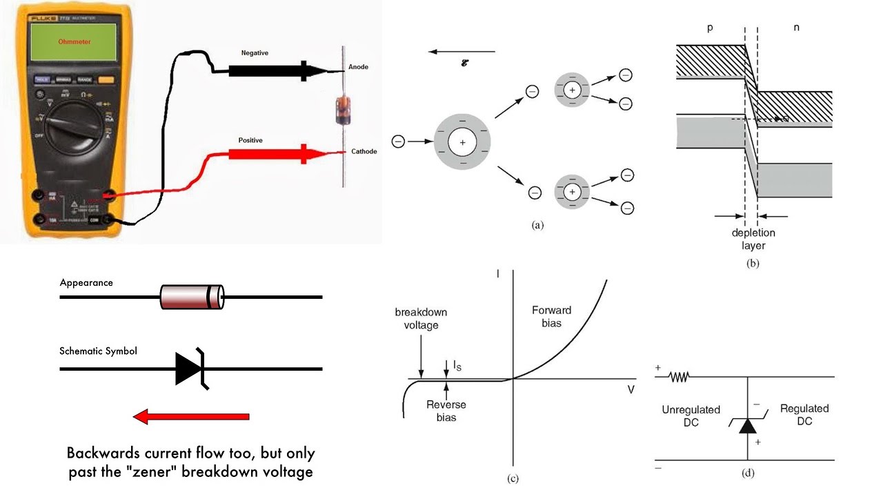
Zener diode is nothing but a single diode connected in a reverse bias, we have already stated that. This is exactly the right answer for many. Note that the symbol is similar but somewhat the block diagram below shows an ac input voltage connected to a rectifier circuit that converts the ac input into a d voltage.
This is the circuit diagram of zener diode tester which tests zener diodes with breakdown voltages extending up to 120 volts.
Draw the schematic diagram for the circuit to be analyzed. This variable zener diode circuit acts like a zener diode with a breakdown voltage adjustable in a vast domain. The above figure is the circuit diagram of zener diode. This is a handy circuit and will help you to measure the zener diode easily.