You recognize the way some components are connected and identify known pieces of the schematic.
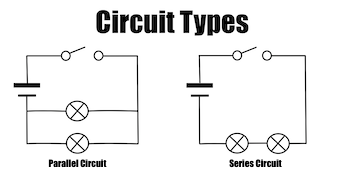
View Schematic Diagram Of Parallel Circuit And Series Circuit Gif. The resulting electrical network will have two terminals, and itself can participate in a series or parallel topology. Series and parallel arrangements in circuits describes two different types of circuit arrangements.
Circuit Diagrams For Kids | Kids Matttroy from study.com
Schematics and circuit diagrams are commonly used in engineering diagrams. The crucial difference between series and parallel circuit exist on the basis of orientation of the components in the circuit. Circuit diagrams or schematic diagrams show electrical connections of wires or conductors by using a node as shown in the image below.
Electrical tutorial about parallel rlc circuits and analysis of parallel rlc circuits that contain resistor, inductor and capacitor and like the series rlc circuit, we can solve this circuit using the phasor or vector method but this time the vector diagram will have the voltage as its reference with.
Each arrangement provides a different way for electricity to flow through a circuit. The crucial difference between series and parallel circuit exist on the basis of orientation of the components in the circuit. The pictorial style circuit diagram in conjunction with circuit diagram symbols, there are also a series of different types of line styles to connect objects. Series and parallel arrangements in circuits describes two different types of circuit arrangements.