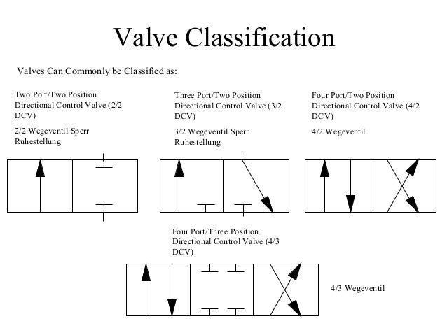
The following are different spool positions of schematic symbols that are commonly used in directional control valves.
View Hydraulic Valves Schematic Symbols Images. Laying each symbol out on the page in the same sequence the components are used in the circuit allows people. This is a very simple animated illustration on the basics of hydraulic schematic symbols.
心に強く訴える Check Valve Symbol Hydraulic - 矢じり from image.slidesharecdn.com
Some valves can be pressure. Hydraulic symbols provide a clear representation of the function of each hydraulic component. A warmer than normal tank return line on a relief valve indicates operation at relief valve setting.
By understanding the five basic hydraulic symbols discussed here you will be able to understand many of the other symbols.
1 typical wiring schematic 2 location pin (refer to section hole pattern for position) 3 filter 4 4x ø. Depending on which of the valve blocks is in function, the gas is directed to port a or b as shown by. Valves are the most complicated symbols in fluid power systems. Huge lists of hydraulic symbols are available as per the iso hydraulic symbol glossary.