Therefore, the transfer function of the system is.
Get Schematic Block Diagram Of Single Input Multiple Output Wireless System Background. Today's wireless communication systems require: Typical system schematic with one nmos selector and schottky diode.
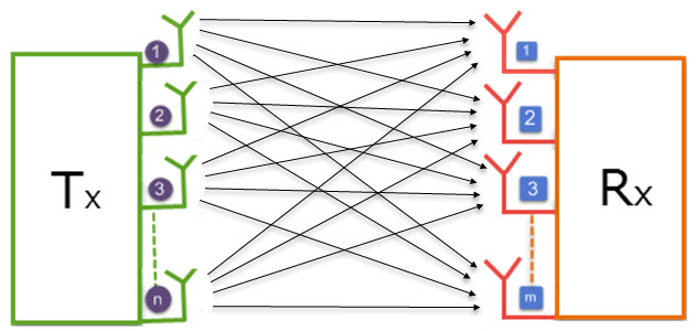
MIMO - Learn Abount Multiple Input and Multiple Output ... from www.elprocus.com
Block diagram of a wireless link with turbo coding and multiple receiving antennas. When an instruction is being processed, other current processes are terminated. Qam the block diagram of the system under consideration is modulator is considered with maximum likelihood decoding.
When stb is high, clk is ignored.
Serial management interface data input/output serial management interface clock. Fig.1 shows the block diagram of a general communication system, in which the different functional elements are represented by blocks. Qam the block diagram of the system under consideration is modulator is considered with maximum likelihood decoding. This includes ac schematics and dc schematics and diagrams that prominently feature relaying.