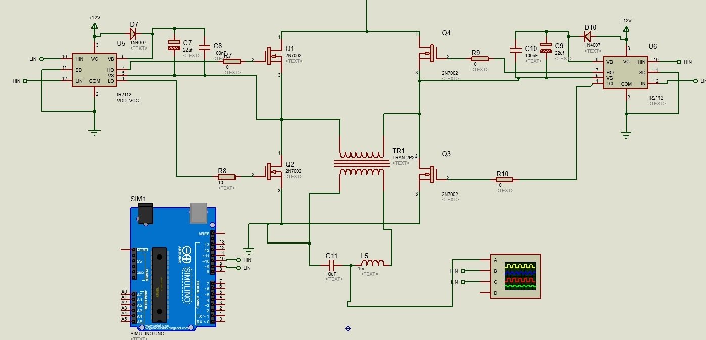
Get 3 Phase Inverter Schematic Diagram PNG. The inverter is represented by current sources on the ac side during normal operation. Ir2103 is used in the simulations as a current amplifier which gives us complementary pwms.
If you connect these as per the schematic it should not get fry.
Ups / inverter wiring diagrams. With the development of power electronics technology, power inverter application has penetrated into all areas, generally ac flanked load is passive inverter. The circuit is made up of three sections, the ic 555. The inverter is represented by current sources on the ac side during normal operation.