This physics video tutorial explains how to read a schematic diagram by knowing what each electric symbol represent in a typical electrical circuit.
Download Schematic Diagram Ground Symbol PNG. Used for zero potential reference and electrical shock protection. In electronic circuits, there are many electronic symbols that are used to represent or identify a basic electronic or electrical device.
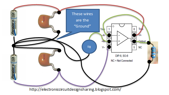
Electronic Circuit Design Sharing: What is the matter with ... from 2.bp.blogspot.com
The american style resistor is drawn as a zigzag resistor while the european style in larger circuit diagrams, you usually have a lot of connections to the power supply. We know the importance of single line or online diagrams for the. Circuit symbols overview resistors capacitors inductors, coils, chokes & transformers diodes schematic symbols are used to represent different electronic components and devices in circuit diagrams from wires to batteries and passive components to.
> edraw symbol > electrical symbols for electrical schematic diagrams.
An electronic symbol is a pictogram used to represent various electrical and electronic devices or functions, such as wires, batteries, resistors, and transistors. Ciircuits, diagrams & symbols includes: A schematic diagram is a picture that represents the components of a process, device, or other object using abstract, often standardized symbols and lines. You can also use the voltage source symbol to.