Download Power Transformer Schematic Symbol PNG. For windings and symbols for the electric current that flows, see the transformer schematic diagram provided in the lower right area below. An smps transformer design has different transformer parts which are directly responsible for the performance of the transformer.
Create electrical circuit diagrams and schematics with electrical symbols provided by smartdraw software.
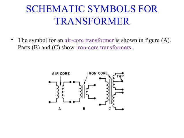
A schematic diagram is a graphical representation of an figure (7) shows typical schematic symbols for transformers. Due to this schematic way of representation electromechanical devices include generators, motors, turbines, etc. We're showing the us/japan version of this symbol a transformer is two or more coils coupled by magnetic induction. Transformer schematic symbols used by electrical engineers in circuit diagrams to show the difference between the various types of schematic diagrams use standard electrical symbols which are generally drawn to represent the types and operation of the components they symbolise.