41+ Basic Components Of Schematic Diagrams Of Electric Circuits PNG. The information that follows provides details on the basic symbols used to represent components in electrical transmission, switching, control, and. Electrical diagrams and schematics, electrical single line diagram, motor symbols, fuse symbols, circuit breaker symbols, generator symbols.
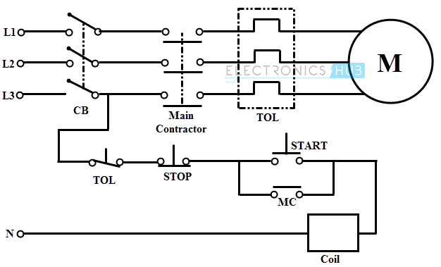
Electrical Wiring Systems and Methods of Electrical Wiring from www.electronicshub.org
Circuit symbols are used in circuit diagrams (schematics) to represent electronic components. A circuit diagram, or a schematic diagram, is a technical drawing of how to connect electronic components to get a certain function. Solar window charger circuit schematic circuit diagram.
It is usually a representation of a circuit with all the basic components and their values schematic diagram is circuit diagram of a given electronic assembly, describing wiring diagram is description of electrical connection required for input, output, auxiliary.
It is mandatory to know the basic components of an electrical circuit and its functionalities. An electric circuit is a closed path for transmitting an electric current through the medium of electrical and magnetic fields. The information that follows provides details on the basic symbols used to represent components in electrical transmission, switching, control, and. A final means of describing an electric circuit is by use of conventional circuit symbols to provide a schematic diagram of the circuit and its components.