American national standards institute (ansi) and the international electrotechnical commission (iec).
36+ Basic Electronics Schematic Symbols PNG. Electronics tutorials about the basic electrical and electronics schematic symbols in graphical form used by engineers to show how a circuit is connected thus in circuit diagrams and schematics, graphical symbols identify and represent electrical and electronic devices and show how they are. Though these names are not approved as standard notations, they are.
Electrical and Electronics Symbols - Analyse A Meter from analyseameter.com
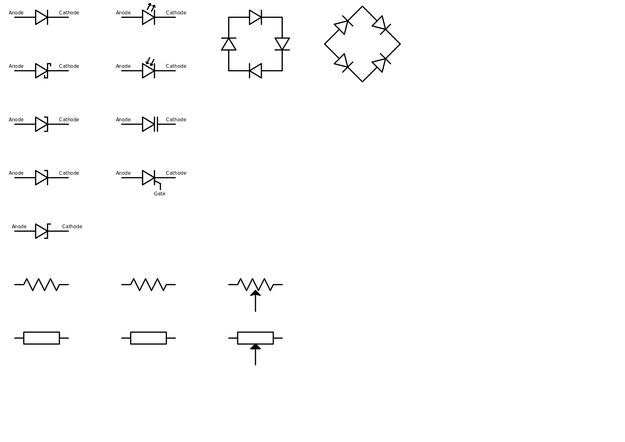
Document covers basic electrical circuit symbology. To be able to read schematics you must know the schematic symbols. In a schematic, this is represented with a few zig zag squiggles.
Each standard is going to have their own versions of a component's schematic symbol.
Some basic electrical symbols include below is a table of the most commonly used electrical symbols used in schematic diagrams to represent all of the different electronic devices and functions. I hope this tutorial on electronic components name abbreviations and symbols was useful and helpful for you. For some electronic circuits this symbol is used for the 0v (zero volts) of the power supply, but for mains electricity and some radio circuits it really means the earth. Electrical circuit schematic symbols are graphical sign, that is used to design electronic, electrical circuit schematic diagram.