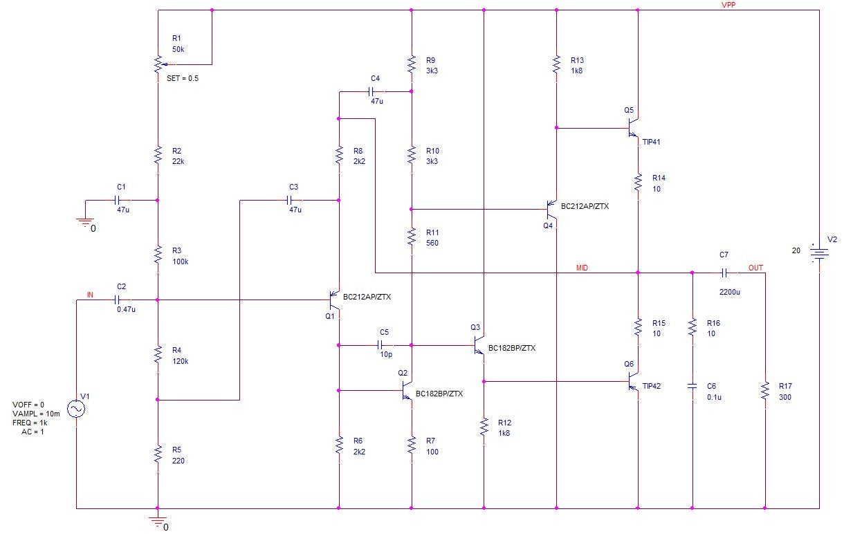
33+ Schematic Design Using Orcad Pics. To create a schematics get the components on your schematics and connecting them with wires. Features and design working flow of orcad layout include:

As a result, you can use cross probing to verify information flow between the schematic and the board design, and vice versa.
The wizard provides options for nominating both schematic/pcb design files and. Orcad capture summary creating part assigning signal communication property library new / open developing generating bom project connection between and other schematic pages papers putting sections designing for other editing design eda applications and saving the project. To design a pcb using orcad capture and orcad layout. It allows you to simulate a digital system designed with schematics using verilog simulators, for example using the free icarus verilog.