33+ Basic Hydraulic Schematic Symbols PNG. Schematic symbols and circuit design help. All basic hydraulic symbols with explanation of reading hydraulics circuits.
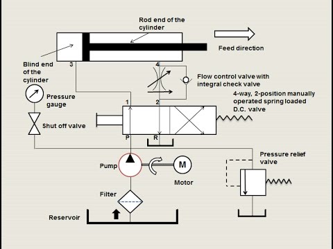
Hydraulic circuits can be comprised of an infinite combination of cylinders, motors, valves, pumps the complexity of these components are difficult to represent fully, so a family of graphic symbols have been developed to represent fluid power components and systems on schematic drawings.
There are many electronic symbols in electronic circuits that are used to represent or identify a basic electronic read also>> plumbing pipe and fitting symbols read also>> hydraulic and pneumatic schematic symbols read also. The basic flow control symbol is a representation of a restrictor. Let's review some common symbols you may come across. The following pages illustrate and give a brief description for some of the more.