Wires can connect two terminals together, or they can connect dozens.
27+ Schematic Symbol Of Connecting Wire Pics. All circuit symbols are in standard format and can be used for drawing schematic circuit diagram and layout. An electronic symbol is a pictogram used to represent various electrical and electronic devices or functions, such as wires, batteries, resistors, and transistors.
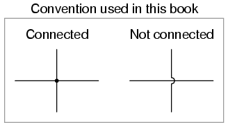
Wires and Connections | Circuit Schematic Symbols ... from sub.allaboutcircuits.com
When you add a wire connection, you select the style and the direction the wire connects from. Each standard is going to have their own versions of a component's schematic symbol. Wiring diagrams use simplified symbols to represent switches, lights, outlets, etc.
I was looking at some connector symbols today and noticed that there is quite some difference in styles.
You could build a real circuit based on either of these schematics. The first is the crimp (pin/socket) that will be embedded in the connector head as stated previously, the connector head is connected on one side while the other side continues the wire up to the cable. Most of the electrical schematic symbols for data, phone, tv and sound used on blueprints have become standard. We know the importance of single line or online diagrams for the.