But instead of using text to explain the recipe, a drawing is used.
25+ Schematic Design Electrical Gif. Electrical diagrams and schematics, electrical single line diagram, motor symbols, fuse symbols, circuit breaker symbols, generator symbols. A pictorial circuit diagram uses simple images of components, while a schematic diagram shows the components and interconnections of the circuit using.
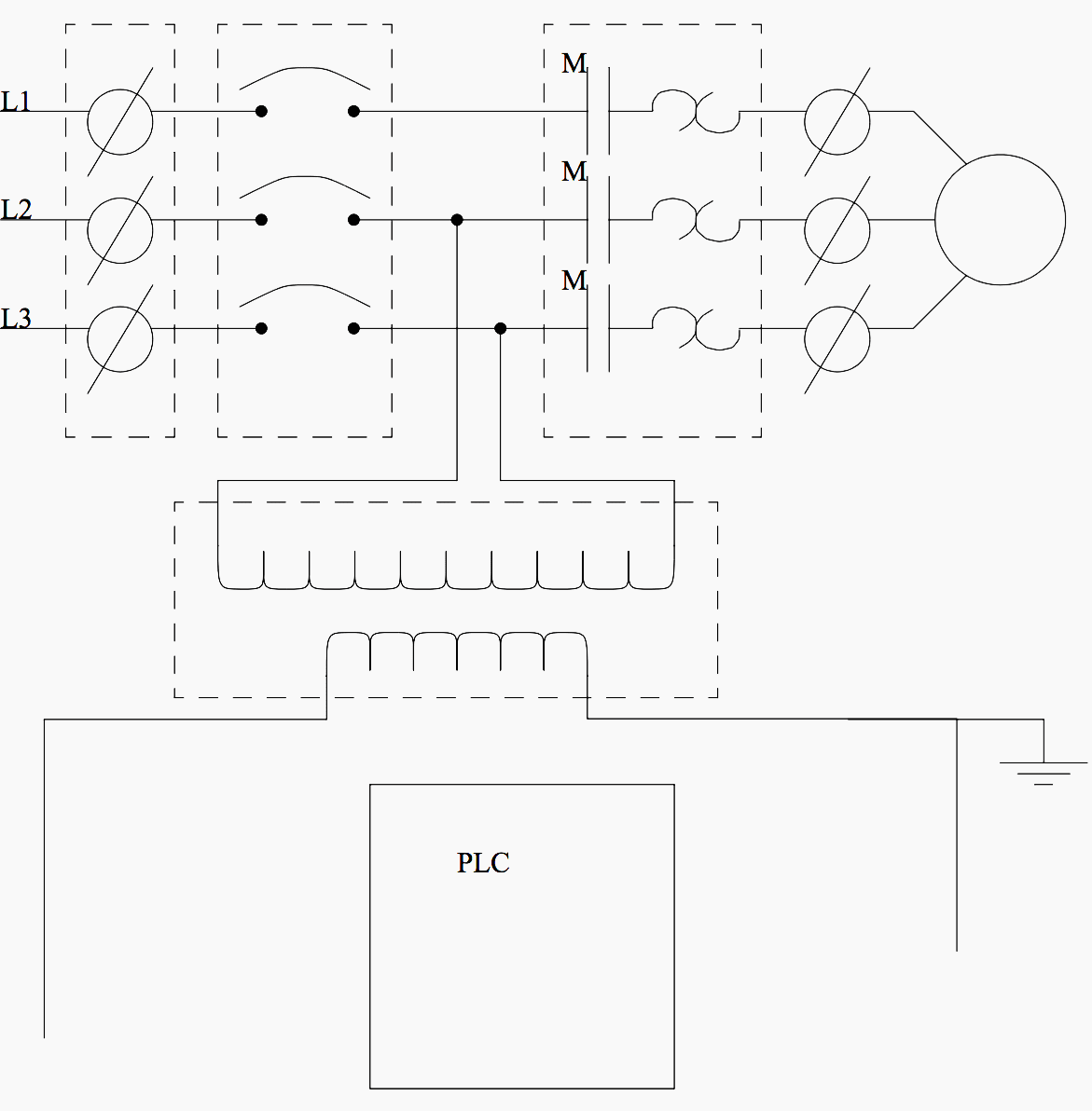
Basic electrical design of a PLC panel (Wiring diagrams) | EEP from electrical-engineering-portal.com
They are pictogram that shows instead of electronic devices for circuit design and more. Circuit schematics are the bridge between conceptual electrical design and physical realization of a printed circuit board assembly, or pcba. E3.schematic makes electrical design smarter, here's how.
This article shows many of the frequently used electrical symbols for drawing electrical diagrams.
The above fm transmitter design is a result of many hours of testing and tweaking. Once you use integrated schematic capture, you can start your circuit board layout and create real circuit boards. When you have your electronic schematics for what you want to build, the rest is all about just following the recipe. An electronic schematic is a diagram that uses standardized electronic and electrical symbols to show how individual components are connected together in a circuit.